
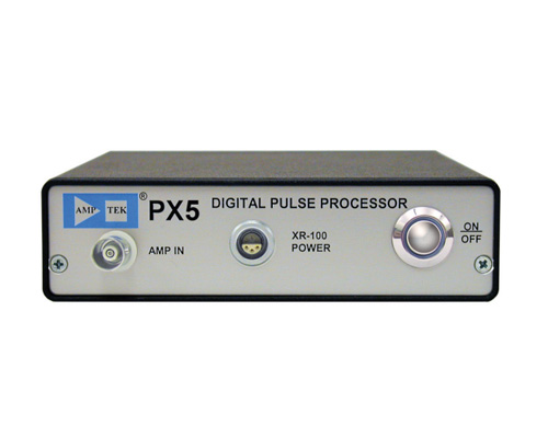
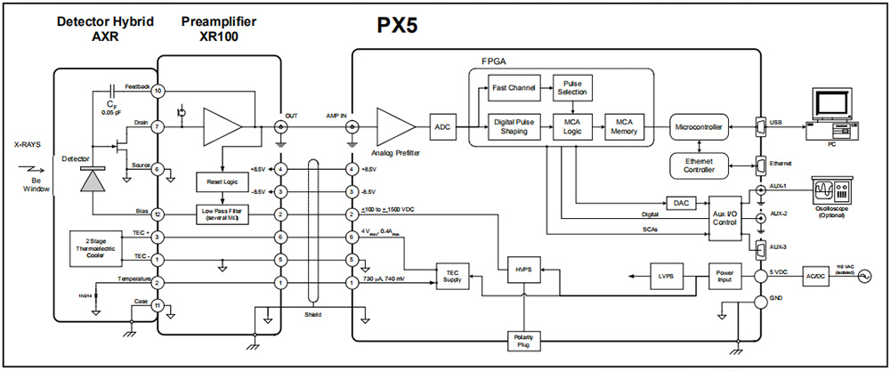
The Amptek PX5 interfaces between (1) an X-ray and gamma-ray detector with its preamplifier and (2) a computer running data acquisition and control software. Designed principally to support Amptek s XR100 series of SDD, Si-PIN, and CdTe detectors, it can be used with many other radiation detectors and preamplifiers, including HPGe detectors. It is compatible with both reset and feedback preamplifiers of either polarity. The PX5 includes (1) a high performance digital pulse processor (replacing a conventional shaping amplifier), (2) a multichannel analyzer, and (3) both low and high voltage power supplies (±10).
| Features | Applications |
| ? Includes digital pulse shaping amplifier, MCA, and power supplies | ? X-ray and gamma ray detectors |
| ? Compatible with all Amptek SDD, Si-PIN, and CdTe-diode detectors | ? Nuclear Instrumentation |
| ? Supports detectors from other manufacturers, and both reset and feedback preamplifiers of either polarity | ? Portable, battery operated systems |
| ? Highly configurable | ? OEM & Special Applications |
| ? Trapezoidal, and new Cusp shaping with wide range of peaking times to optimize performance | ? Process Control |
| ? High count rate capability with excellent baseline stability, throughput, and pile-up rejection | ? Research and Teaching |
| ? Up to 8k output MCA channels | |
| ? Oscilloscope mode - DAC output for pulse monitoring and adjustment | |
| ? 8 single channel analyzer outputs | |
| Communications | Power |
| ? Interfaces: RS-232, USB, Ethernet, I2C, auxiliary | ? High voltage bias adjustable ±100V to ±1.5 kV (Higher voltages available as a custom option.) |
| ? Software for PC data acquisition and control | ? Thermoelectric cooler with feedback |
| ? Software Developer’s Kit included (SDK) | ? Operates from +5 V DC supply (AC power adapter included) |
| Pulse Processing Performance | |
| Gain Settings | Combination of coarse and fine gain yields overall gain continuously adjustable from x0.75 to x516. |
| Coarse Gain | 16 log spaced coarse gain settings from x0.75 to x413. |
| Fine Gain | Adjustable between 0.75 and 1.25, 10 bit resolution. |
| Full Scale | 1000 mV input pulse @ x1 gain. |
| Gain Stability | <30 ppm/°C (typical) |
| ADC Clock Rate | 20 or 80 MHz, 12 bit ADC |
| Pulse Shape Trapezoidal or Cusp | Semi-Gaussian amplifier with shaping time τ has peaking time of 2.4 τ and is comparable in performance with the trapezoidal shape of the same peaking time. |
| Peaking Times | 30 software selectable peaking times between 0.1 and 102 μs,corresponding to semi-Gaussian shaping times of 0.04 to 42.5 μs. |
| Flat Top Times | 16 software selectable values for each peaking time (depends on the peaking time), >0.05 μs. |
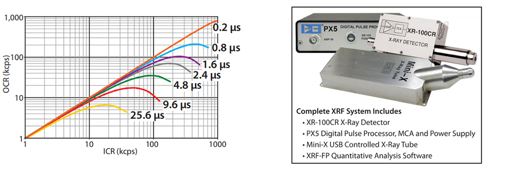
| Max Count Rate | With a peaking time of 0.2 μs, 4 MHz periodic signal can be acquired. |
| Dead Time Per Pulse | 1.05x peaking time. No conversion time. |
| Fast Channel Pulse Pair Resolving Time | 120 ns |
| Pile-Up Reject | Pulses separated by more than the fast channel resolving time, 120 ns, and less than 1.05x peaking time arerejected. |
| Baseline Restoration -Asymmetric | 16 software selectable slew rate settings. |
| Rise Time Discriminator (RTD) | The dpp can be programmed to select input pulses based on their rise time properties. |
| MCA Performance | |
| Number of channels | Commandable to 256, 512, 1k, 2k, 4k, or 8k channels. |
| Bytes per channel | 3 bytes (24 bits), 16.7 M counts. |
| Preset Acquisition Time | 10 ms to 466 days. |
| Data Transfer Time | USB: 1k channels in 12 ms; RS-232: 280 ms |
| Conversion Time | None |
| Presets | Time, total counts, counts in an ROI, counts in a channel. |
| MCS Timebase | 10 ms/channel to 300 s/channel |
| External MCA Controls Gate Input | Pulses accepted only when gated on by external logic. Input can be active high or active low. |
| Counters | Slow channel events accepted by MCA. Incoming counts (fast channel counts above threshold), event rejected by selection logic, and external event counter. |
| Hardware | |
| Microprocessor | Silicon Labs 8051F340 8051-compatible core. |
| External Memory | 512 kb low-power SRAM |
| Firmware | Signal processing is programmed via firmware, can be upgraded in the field. |
| Communications | |
| RS-232 | Standard serial interface, 115 or 56 Kbaud. |
| USB | Standard 2.0 full speed (12 Mbps). |
| Ethernet | Standard 10base-T. |
| Connections | |
| Analog Input (BNC) | The analog input accepts positive or negative going pulses from a charge sensitive preamplifier. |
| Power | +5 VDC. Mates with a center positive 5.5 mm x 2.1 mm power plug. |
| USB | Standard USB mini-b jack. |
| Ethernet | Standard Ethernet jack. |
| AUX-1 (BNC) | Configured in software as (1) an analog output, to view shaped pulses or diagnostic signals, (2) a digital output, to view a discriminator output or diagnostic signals, or (3) a digital input. |
| AUX-2 (BNC) | Configured in software as (1) a digital output, to view a discriminator output or diagnostic signals, or (2) a digital input, to gate or synchronize data acquisition. |
| AUX-3 (BNC) (15 pin D connector female) | Includes: (a) the lines for a serial RS232 interface, (b) two lines which can be configured for digital inputs or outputs, (c) 8 single channel analyzer (SCA) outputs, (d) a control line to command the power on or off remotely. |
| XR100 Power: 6-Pin Lemo Connector | |
| 1 | Temperature |
| 2 | Bias (up to ±1500 V) |
| 3 | -8.5 or -5 VDC |
| 4 | +8.5 or +5 VDC |
| 5 | Cooler - (grounded) |
| 6 | Cooler + |
| Ground on Shield | |
| Power | |
| +5 V | +5 VDC at 500 mA (2.5 W) typical. Current depends strongly on Tdet, ranging from 300 to 800 mA at 5 VDC. |
| Input Range | +4 V to +5.5 V (0.4 to 0.7 A typical) |
| Initial Transient | 2 A for <100 ns |
| Auxiliary Inputs and Outputs | |
| The connectors bring out logic signals which are not required for the primary use of the PX5: acquiring spectra and transmitting them over the serial interface. These are generally “l(fā)ow level” logic signals associated with each pulse processed by the PX5; used for synchronizing the PX5 data acquisition to external hardware and for direct counter/timer outputs from the PX5. The signals are described below. | |
| Single Channel Analyzers | 8 SCAs, independent software selectable LLDs and ULDs,LVCMOS (3.3 V) level (TTL compatible). |
| Digital Outputs | 2 independent outputs, software selectable between 8 settings including INCOMING_COUNT, PILEUP MCS_TIMEBASE,etc. LVCMOS (3.3V) levels (TTL compatible). |
| Digital Inputs | 2 independent inputs, software selectable for MCA_GATE,EXTERNAL_COUNTER. |
| DAC Output | Used in oscilloscope mode to view the shaped pulse and other diagnostic signals. Range: 0 to 1 V. |
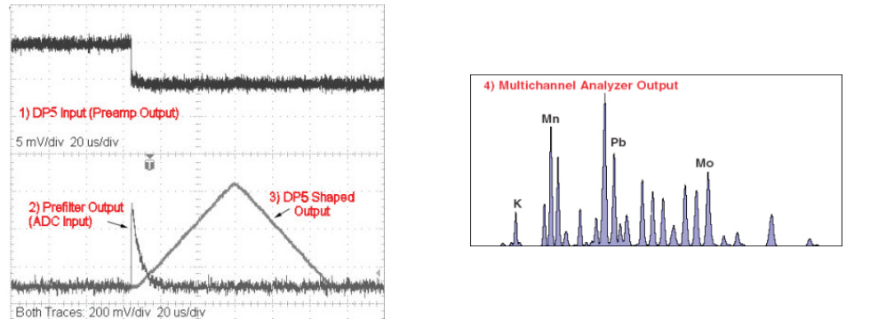
| Digital Oscilloscope | Displays oscilloscope traces on the computer. Software selectable to show shaped output, ADC input, etc., to assist in debugging or optimizing configurations. |
| Software | |
| DPPMCA data acquisition, display, and control software is included. Also available for download and updates on Amptek’s Software Download page. ? Full control of all hardware features, including acquisition presets, gain, peaking time, detector HV, detector temperature, number of channels, risetime discrimination parameters, and many more. ? Live display of the spectrum with many options. Can show up to 8k channels, with either integrating or delta mode. Includes linear and logarithmic vertical scaling, manual or auto-ranging, and zoom on the horizontal scale. Displays live spectrum and multiple stored or processed spectra. ? Spectral analysis features include energy calibration, setting regions of interest (ROI), computing ROI information (centroid, total area, net area, FWHM), spectrum smoothing, summing of spectra, subtraction and scaling of background spectra. ? Active link to the XRF-FP Quantitative Analysis Software Package using fundamental parameters, which can be purchased separately. ? Supports Microsoft Windows XP, Vista, and Windows 7.For users wishing to write custom software, a software developer’s kit is available. | |
| General and Environmental | |
| Operating Temperature | -40 °C to +85 °C. |
| Warranty Period | 1 year |
| Typical Device Lifetime | 5 to 10 years, depending on use |
| Long-term Storage | 10+ years in dry environment |
| Typical Storage and Shipping | -40 °C to +85 °C, 10 to 90% humidity non-condensing |
| Compliance | RoHS Compliant |
 | TUV Certification Certificate #: CU 72112987 01 Tested to: UL 61010-1: 2004 R10.08 CAN/CSA-C22.2 61010-1-04+GI1 (R2009) |
| Physical | |
| Size | 6.5” x 5.5” x 1.5” / 165 x 135 x 40 mm |
| Weight | 1.6 lbs / 750 g |
| Digital I/O: 15 pin D connector (female) | |
| 1.Ground | 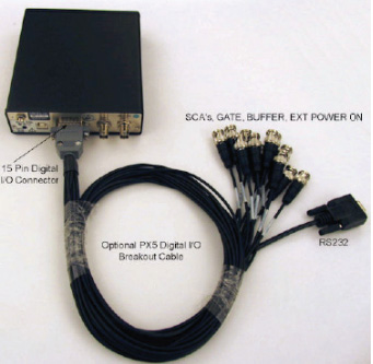 |
| 2.RS232-TX | |
| 3.RS232-RX | |
| 4.SCA 6 Out | |
| 5.SCA 5 Out | |
| 6.Ground | |
| 7.Aux 3 | |
| 8.Aux4 | |
| 9.SCA 8 Out | |
| 10.External Power On | |
| 11.SCA 7 Out | |
| 12.SCA 1 Out | |
| 13.SCA 2 Out | |
| 14.SCA 3 Out | |
| 15.SCA 4 Out | |

4. Provides all necessary power for Amptek XR100 detectors.
 微信二維碼
微信二維碼